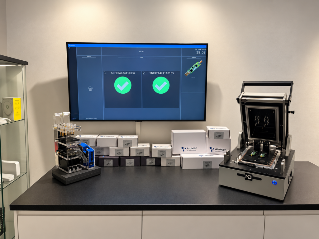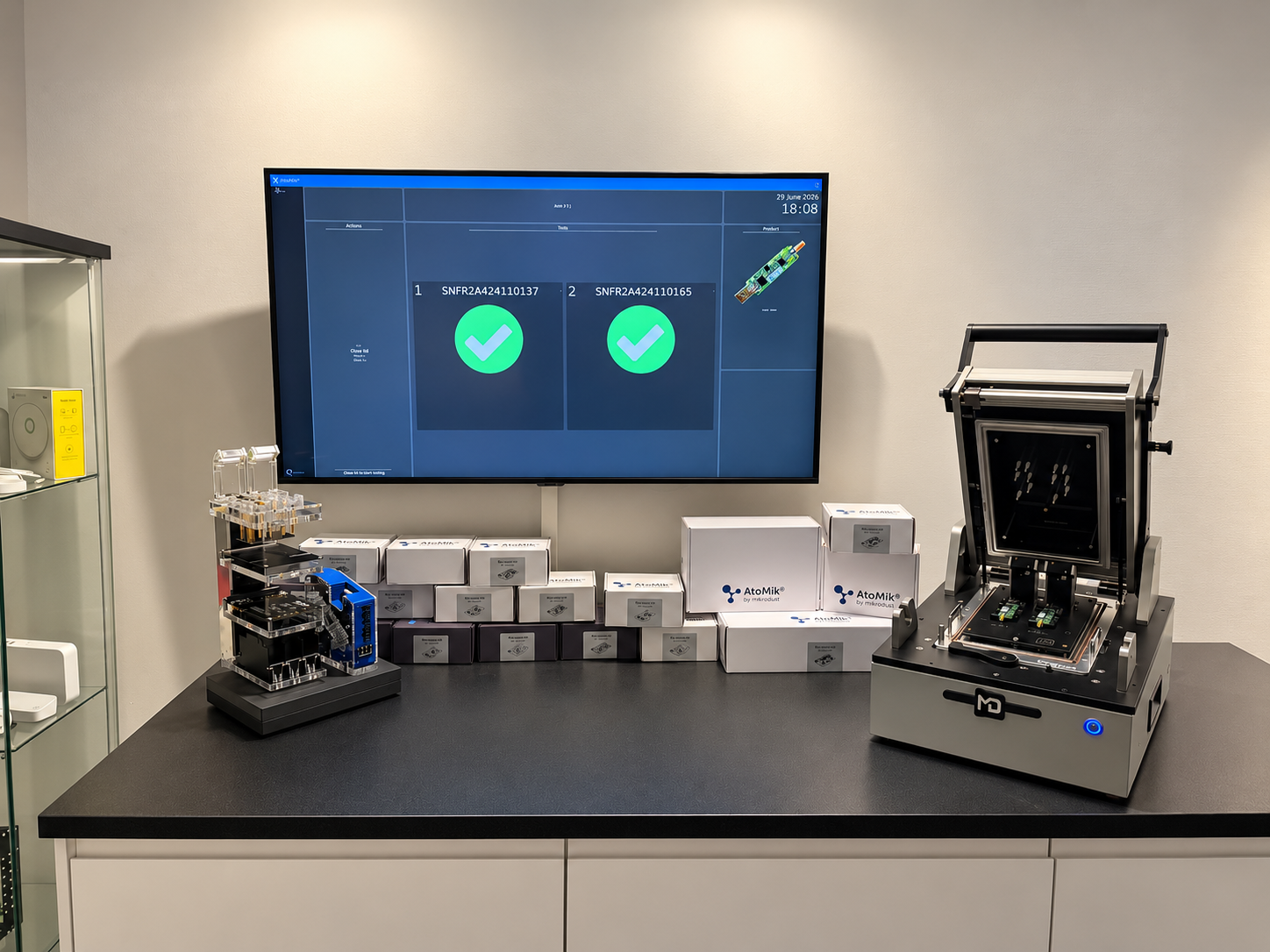
A production radio test fixture must combine consistent RF conditions with instruments for power, programming, digital and analog measurements. This article shows how AtoMik, a compact modular functional circuit test (FCT) platform, places the required instrumentation inside the ingun MA 2111 test fixture, keeping the RF environment consistent while retaining the serviceability needed on the factory floor. The Auris 2 radio sniffer serves as a real production example.
RF fixture design objectives
A production radio test fixture is only useful when the fixture can maintain a consistent environment for the radio measurements. The mechanical interface, cabling, electronics and test sequence therefore need to be designed as one system instead of separate parts loosely joint together. The main objectives are a stable RF environment, with low outside disturbance, where the interference pattern is consistent between test runs and not be affected by servicing the fixture.
EMC Compliance
Legislation in most areas requires test fixtures to fulfil the applicable EMC requirements. These requirements are based on the product not creating unacceptable electromagnetic disturbance and having sufficient immunity against disturbance from its environment.
For an RF production test fixture, the RF shield should be seen as a required part of the design to control the EMC environment. The DUT, RF generator and other electronics in the fixture can generate RF signals that may disturb nearby DUTs, test fixtures or other equipment in the production area. At the same time, RF signals from the surrounding environment can enter the fixture and affect the DUT or the measurement result.
A well-designed RF shield therefore also improves the stability and repeatability of the production test. By reducing unwanted RF interference, the DUT is tested in a more controlled and consistent environment, making the measurement results less dependent on nearby equipment or changes in the production area. This reduces the risk of false failures as well as false passes caused by external interference or RF leakage between test stations.
AURIS 2 RF Fixture Implementation
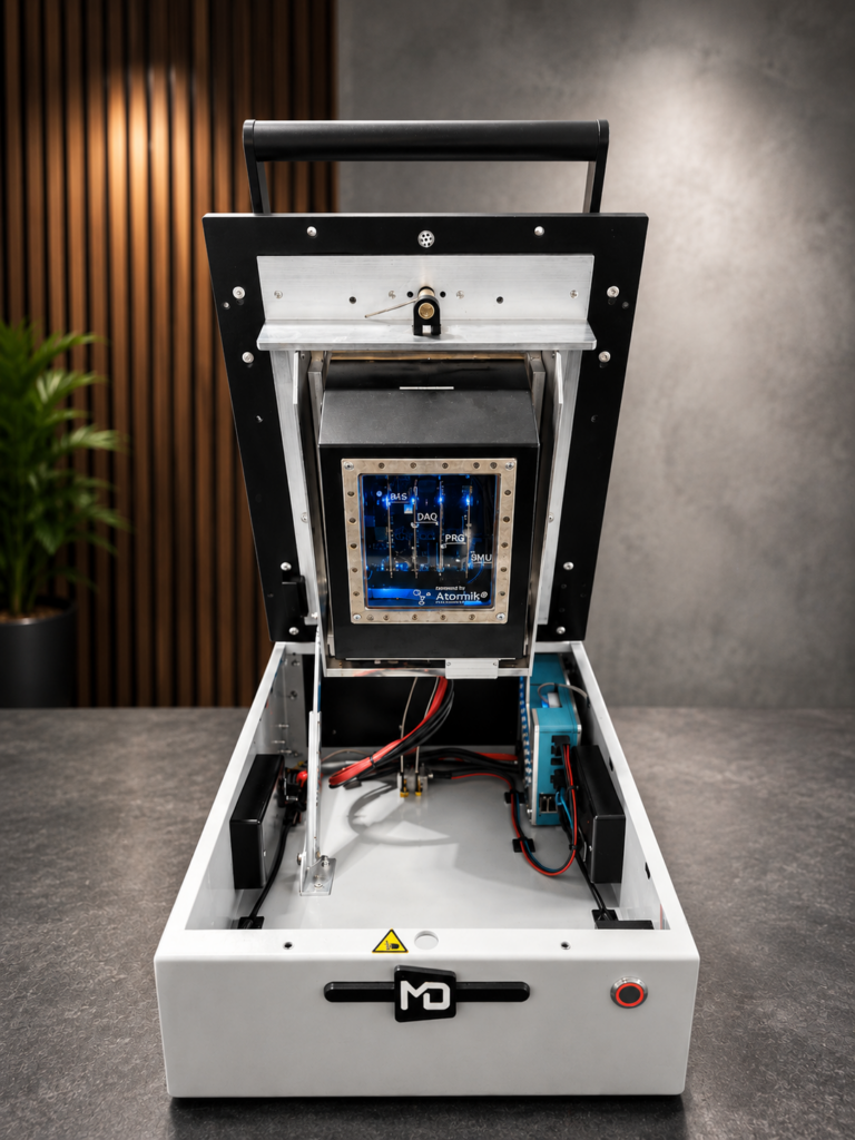
Auris 2 is a radio sniffer developed by Mikrodust and used to capture packets between a gateway and IoT nodes. In this section the fixture used during the production of Auris 2 sniffers will be described.
System setup
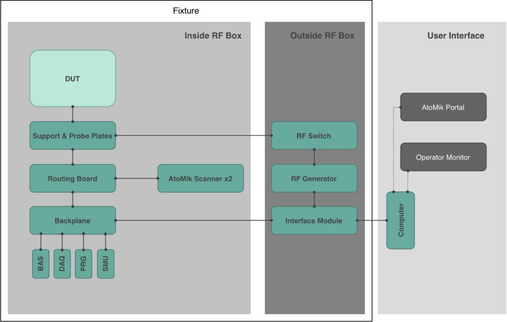
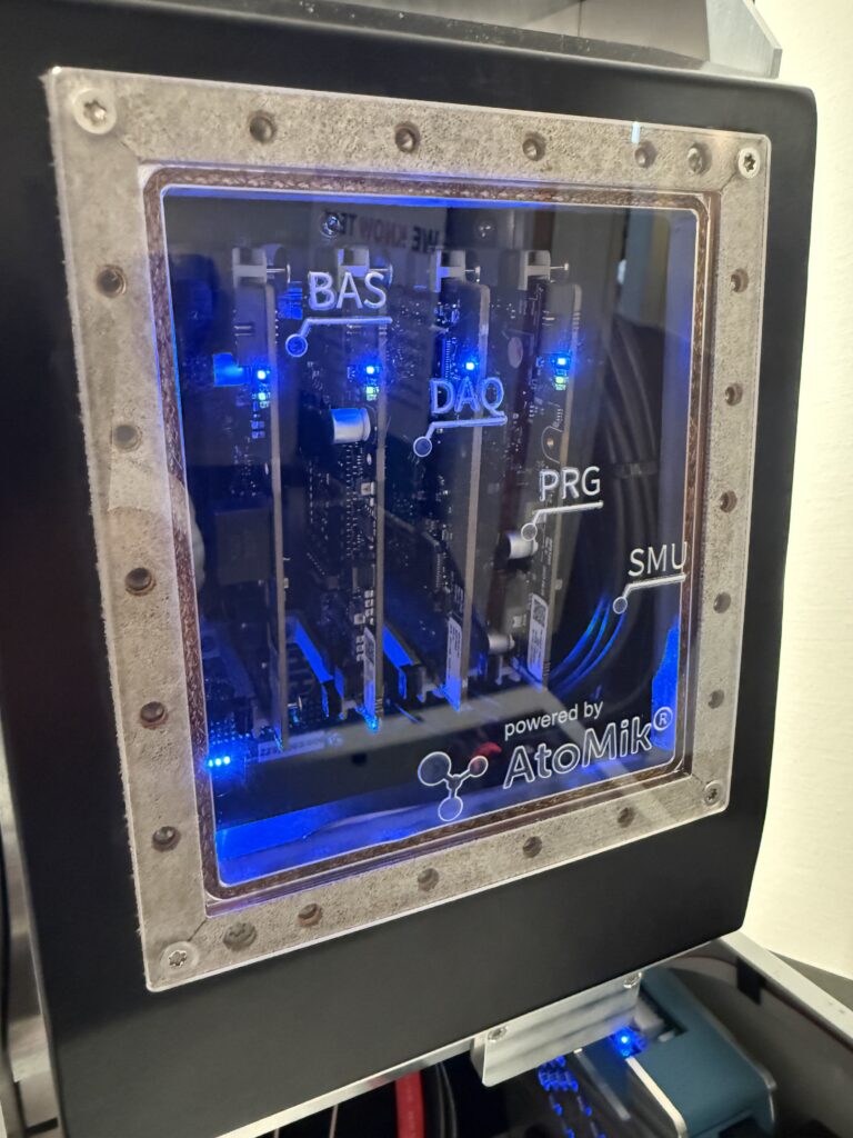
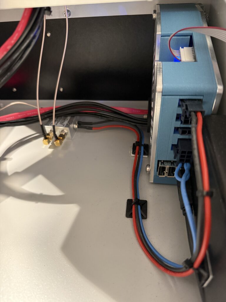
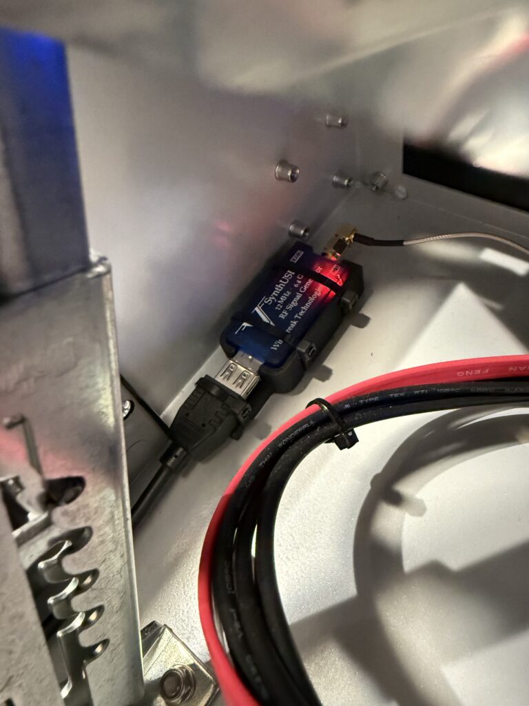
The architecture is divided into three domains representing different areas in the ingun MA 2111 fixture. The DUT, support and probe interface, routing board, scanners and AtoMik backplane with AtoMik instruments are placed inside the RF Shield. The RF switch, USB RF generator and AtoMik Interface Module are inside the fixture but outside the RF Shield. The computer and its accessories remain outside the fixture. The AtoMik portal represents the cloud instance where production-data is stored and is not a physical part in the system.
AURIS 2 test sequence overview
| # | Instrument Operation | Instrument Used | Purpose |
|---|---|---|---|
| 1 | Scan barcode | AtoMik Scanner tower | Retrieve manufacturing data such as serial number associated with the DUT. |
| 2 | Power on DUT | AtoMik SMU | Power on the DUT and measure initial current. |
| 3 | Measure voltages | AtoMik DAQ | Verify power rails and voltages before programming and RF calibration. |
| 4 | Flash factory firmware | AtoMik PRG | Load the controlled production-test firmware through JTAG/SWD. |
| 5 | Measure idle current | AtoMik SMU | Measure idle current. |
| 6 | Write manufacturing data | AtoMik PRG | Program serial numbers and product-specific manufacturing parameters. |
| 7 | Calibrate RF power | SynthUSB3 + RF switch | Route a controlled RF stimulus to the DUT to calibrate. |
| 8 | Measure TCXO | AtoMik DAQ | Verify oscillator frequency. |
| 9 | Write/check EEPROM | AtoMik BAS | Write and read back DUT configuration over the required serial bus. |
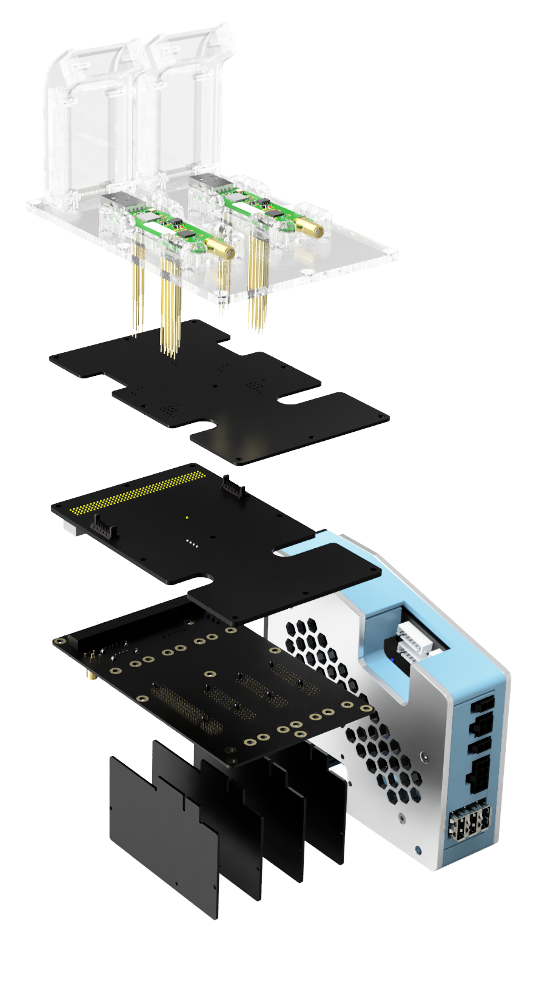
Instrument and accessories used for the Auris 2 test fixture


How AtoMik solves the common issues when testing radio products
Consistent RF environment
The backplane and instrument cards can be mounted directly onto the routing board. This removes the need for cables that would cause inconsistent RF interference when moving around. Even if cables are tied down, they have a tendency to move and if a copy of the fixture is building the cables will never lay in the exact same manner. By utilizing the stack approach with AtoMik the RF environment stays more consistent over time and between fixtures.
Less RF disturbance
A signal that passes through the RF shield introduces disturbance inside the RF shield. By minimizing the number of pass-throughs that are needed, this disturbance can be minimized. AtoMik’s compact footprint enables the fixture builder to place the instrument on the inside of the fixture’s RF shield and therefore minimizing the number of pass-throughs and therefore the external RF disturbance.
Built with expandability in mind
When building an RF fixture, the requirements on the RF-instrument is different from project to project. AtoMik has made sure to have expandability in mind from the start and gives the user access to usb port in all different areas of the test fixture. The AtoMik system gives you USB expandability in all three domains: inside RF Shield, Outside RF Shield and User Interface. This enables the user to choose the best suited RF instrument and place it in the fixture where it makes the most sense for their application.
Standardized parts
Utilizing standard parts, connected by solid PCBs instead of cables, makes the fixture easy to service without accidentally affecting the RF interference pattern inside the fixture. AtoMik’s stack-up removes the need of loose cables and ensures the serviceability is high by having easy to access instruments that connects with a PCIE-slot. With AtoMik being designed with ingun fixtures in mind, the instruments are removable through the service hatch, even in the small RF shield for the MA 2111 fixture.